¶ Introduction
Link's Razor PDM is an advanced, fully programmable microprocessor-controlled Power Distribution Module.
It uses solid-state power devices, upgrading and replacing traditional relays and fuses to simplify wiring and better control power consumers.
Housed in a high-quality, sealed, CNC machined aluminium enclosure, with status LEDs for all 12 outputs, power, and temperature.
Configuration is carried out using the PDM Link PC software, where the user can combine any number of CAN and physical I/O to create a custom power control strategy.
| High Power Outputs | 4 x High power outputs. Highside or lowside drive, half bridge, or paired in full bridge configuration. 25A continuous, 80A max safe peak, PWM capable 10kHz max. |
|---|---|
| Multi-Purpose I/O |
8 x "ADIO" - Analog-Digital-Input-Outputs All 8 capable of analog input and digital/switched input All 8 capable of highside drive on/off output 4 x capable of PWM output. Highside drive only. 10kHz max (ADIO 1-4) 4 x capable of PWM/Frequency/Duty cycle/Speed input. 10kHz max (ADIO 5-8) Software controlled pull-ups (4k7 to 5V) 8A output, overcurrent protected but current limit is not user Max input voltage 12V, max measurable voltage 5V |
| Power |
6 - 24V operating range (across main terminals) 12 and 16 Volt nominal systems supported 4.5V - 5.5V USB (Low power mode, configuration only) <300mA No output static current draw 5V Sensor supply Sensor ground |
| Communication |
USB (C type connector) CAN BUS, user configurable bit rate |
| Physical |
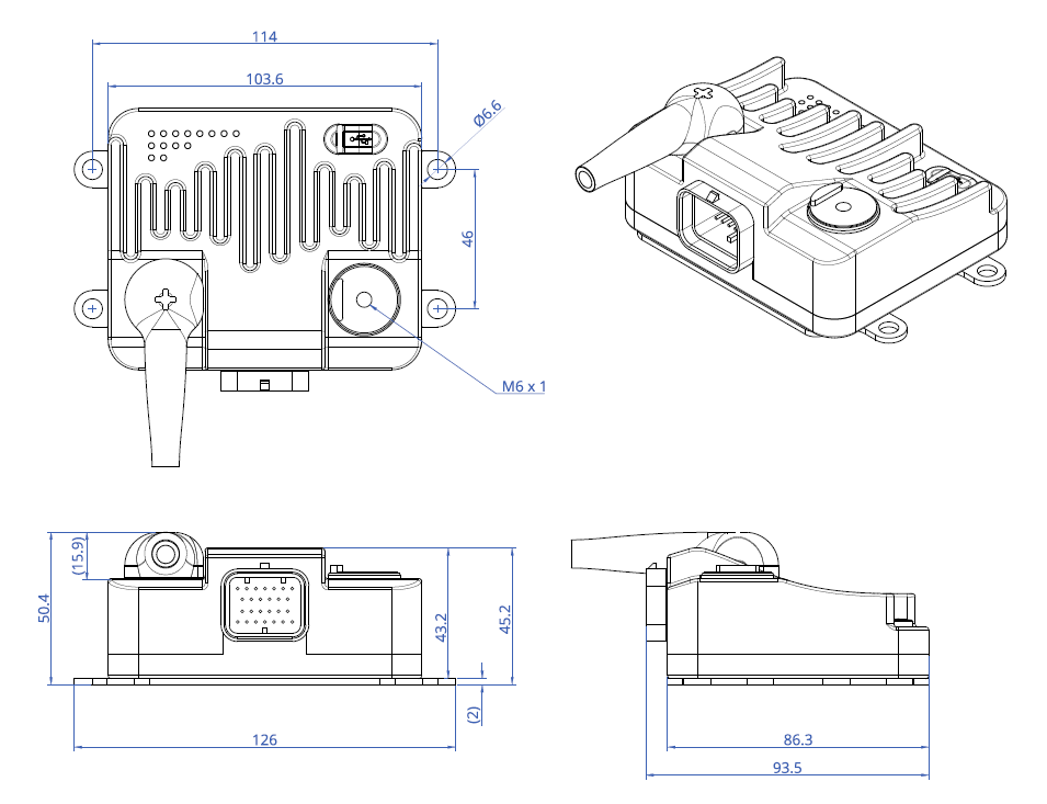
Dimensions - (L) 103.6 mm x (W) 93.45 mm x (H) 43.19 mm Weight - 0.475 kg |
| Environment |
Water resistant -40 to +80 °C operating temperature |
Safety Notice & Disclaimer
Your Link Razor PDM is designed to improve power distribution for a range of applications. Failure to follow all installation and operating instructions may result in damage to the PDM, personal injury, or harm to property. Installation should be carried out by a qualified professional. Link Engine Management will not be held responsible for any damage caused by the incorrect installation of this product. The Razor PDM is not intended to be used on safety-critical systems such as ABS braking, power steering etc.
¶ Installation
¶ Mounting
The PDM is supplied with a bracket to make mounting as easy as possible. Please see the QuickStart guide included in the box for a 1:1 scale template.
Hardware sizes
| PDM Enclosure | M3 |
| Mounting Plate | M5 |
| Main Terminals | M6 |
Although the PDM is environmentally sealed it is recommended to be positioned with the least possible direct contact with the outside environment.
Powering high current devices will generate heat in the PDM. The enclosure of the PDM has been designed to dissipate as much heat as possible, however care should be taken when mounting to ensure it is NOT positioned in an area of extreme heat, close to exhaust systems or engines.
Under large loads, the PDM will get hot, consider PDM location when mounting. If the PDM gets too hot it will turn the outputs off (user definable temperature settings). You can still connect to the PDM via USB to read PDM temperature. If this happens consider changing the mounting location or reducing the loads.
For optimal performance, the temperature of the PDM should be kept as low as possible. This can be done by directly mounting it to a large flat metallic surface with airflow across it (either across the PDM or the mounting surface).
¶ Wiring
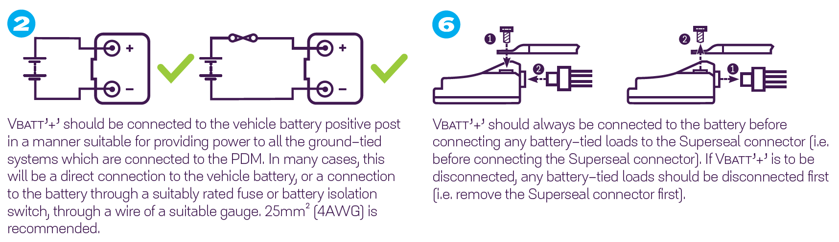
¶ Battery Positive
The battery positive is connected to the PDM via the '+' terminal using the supplied Wurth 967000017 ring terminal and using the specifically designed insulation boot.
The terminals suit 25mm2 (4 AWG) cable.
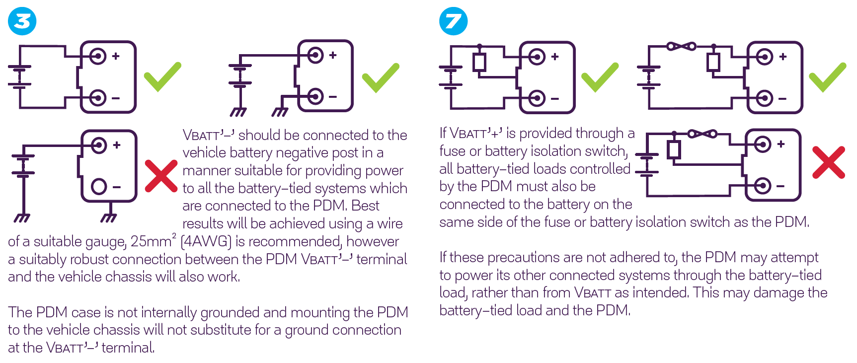
¶ Battery Negative
The battery negative is connected to the PDM via the '-' terminal using the supplied Wurth 967000017 ring terminal. It is recommended the same wire gauge as the '+' terminal be used.
¶ Switched Power and Ground Wiring
Connect IGN SW (Pin 4), to the vehicle switched 12V (ignition). Recommended gauge as per the table below.
SENSOR GND (Pins 6 and 12) are NOT to be connected to battery negative or chassis ground. They are sensor grounds. Recommended gauge as per the table above.
| Output | Recommended Wire Gauge |
|---|---|
| 8 Amp / Signal / GND's / VBATT | 0.85mm² (18 AWG) |
| 25 Amp | 1.25mm² (16 AWG) |
| Battery positive/negative | 25mm² (4 AWG) |
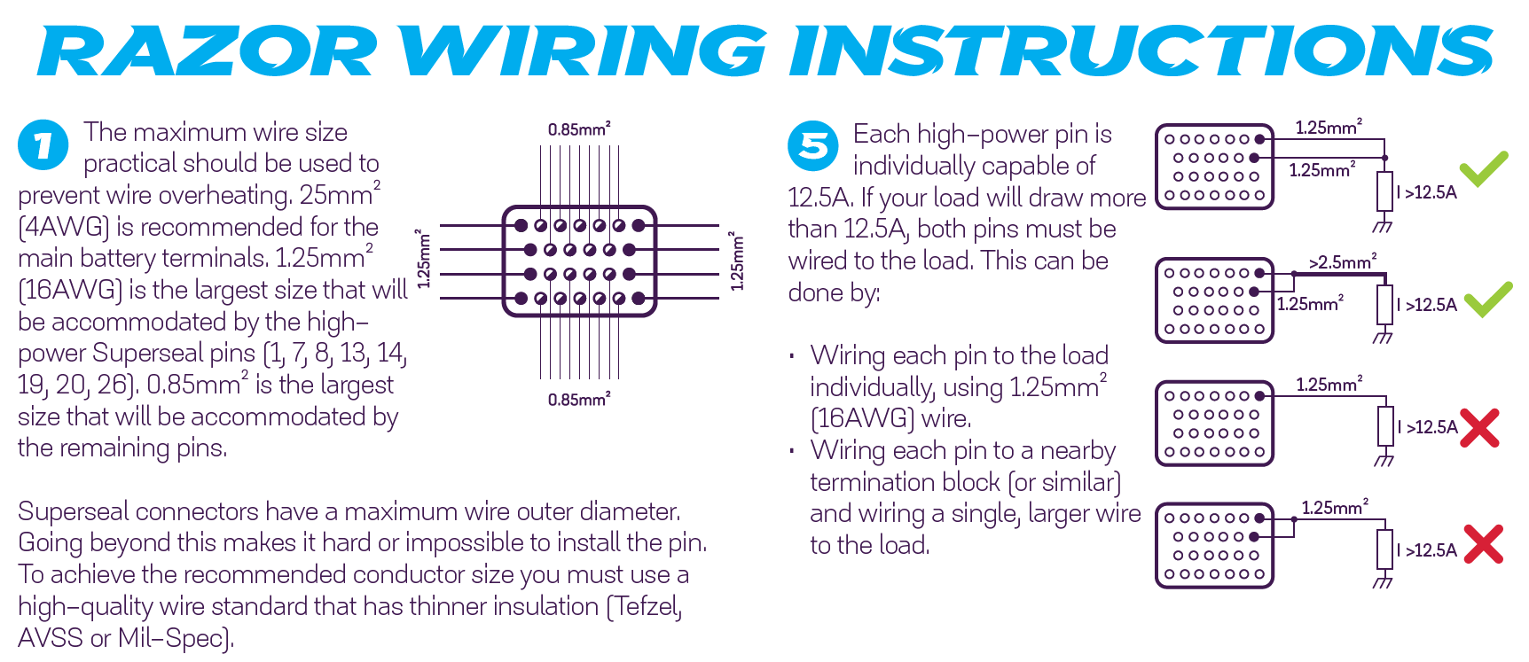
Superseal connectors have a maximum wire outer-diameter, and going beyond this makes it hard or impossible to install the pin. In order to get the largest conductor size, we recommend using a high-quality wire standard that has thinner insulation (Tefzel, AVSS or Mil-Spec).
¶ I/O Wiring
The pins of the Superseal connector are rated to 15 amps each.
- Use pin TE amp Superseal 3-1447221-4
- High power outputs combine two pins to share the current. Use recommended wire gauge as per the table above.
¶ Wiring Information
See PDMLink>Help>Pin connections.
This features the PDM connector pinout as well as a live/exportable pinout table.
This will automatically populate when inputs and outputs are configured and can be exported in CSV format.


¶ CAN Wiring
The PDM will communicate with multiple devices connected to the same CAN bus. The CAN bus should be wired according to CAN requirements.

¶ USB Connection
The PDM can be connected to a PC via USB C. The USB cable will power the PDM to allow configuration of the PDM without having battery + and - connected.
The high power and low power outputs can be configured, but will not operate when the PDM is powered only by USB.
¶ Inputs & Outputs
¶ Inputs
There are 8x "ADIO" Analog-Digital-Input-Outputs.
When configured as inputs they accept variable voltage signals from 0V to +5V. Each input has user-adjustable high and low voltage thresholds for digital input signals. Inputs 5 to 8 are PWM input capable.
Each ADIO has a software configurable 4k7 pull-up to 5V. Pull-up resistors would normally be enabled when using temperature-related sensors and switch-to-ground inputs.
¶ Outputs
¶ High Power
There are 4x high power outputs with a maximum safe inrush current of 80A and a continuous current limit of 25A at 12V.
While the maximum safe inrush current is 80A, the maximum measurable current is 60A.
The high power outputs each share two pins of the 26-pin super seal connector.
They can be used as high-side or low-side drivers, have a max frequency of 10kHz, and can be configured as 4 x half bridges or 2 x full bridges allowing control of devices such as e-wastegates.
When in full bridge mode, Output 1 is paired with Output 2 and Output 3 is paired with Output 4.
Outputs can be joined together to allow the use of higher current devices.
¶ Low Power
The 8x ADIOs can be configured as low power outputs able to deliver 8A at 12V. They can be used as a high-side drive only. Outputs 1 to 4 are PWM output capable.
Outputs can be joined together to allow the use of higher current devices.
¶ Sensors
Sensors should be powered via the PDM SENSOR 5V output pins.
- The 5V output pins are designed for 50mA per pin. Loads above 50mA may result in dropout.
- The two pins are not connected internally, so the user should spread their loads across both pins.
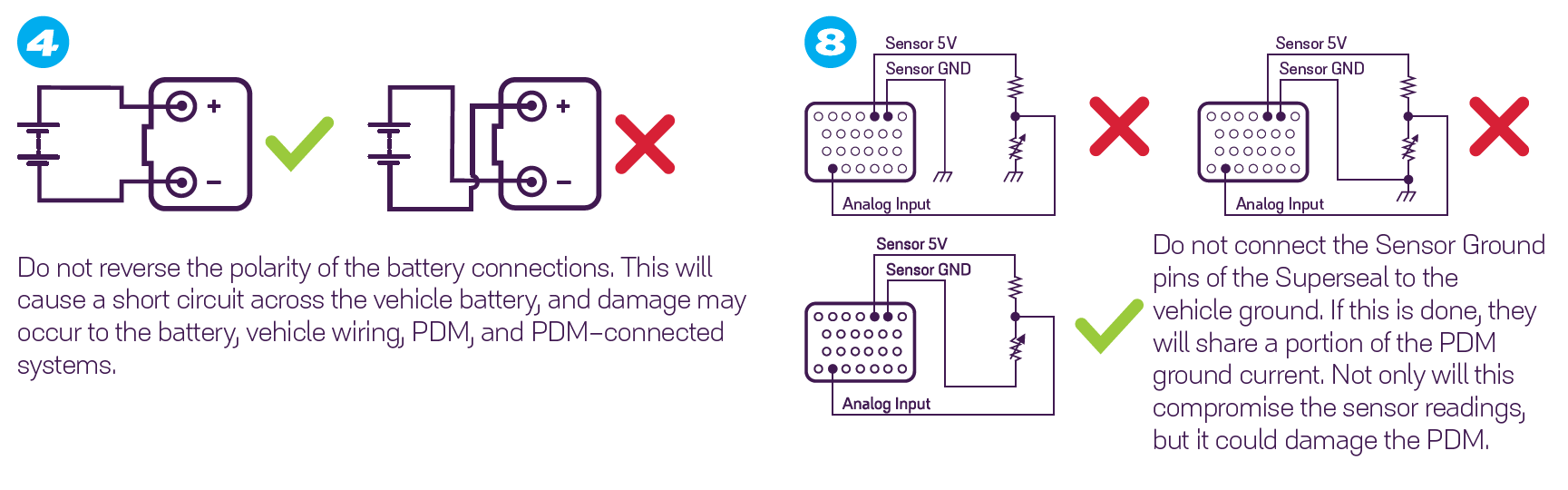
The SENSOR GND pins are provided as a high-quality return for the 5V signals only, DO NOT wire these pins to the vehicle chassis or damage to the PDM may occur.
¶ Protection
All outputs can act as highly programmable electronic fuses. In PDMLink software the user can set parameters to configure:
- how much current will cause the output to trip.
- how long it takes the output to trip.
- how long the output will remain off.
- how many times the output will retry.
- inrush current limits and inrush duration.
¶ High Power Output Protection
All high power outputs feature the following fuse modes:
- Self-resetting fuse mode, Retry, where the pin turns physically OFF for a duration, and then retries up to a set number of times.
- The Retry Count and Delay settings determine self-resetting behaviour.
- Once the Retry Count value is reached, the output will remain in a fault status until the user resets it with a power cycle, a setting change or the status going to inactive and then active.
- Normal fuse mode, Latch Off, where the output latches physically OFF, showing a fault status until the user resets the fuse with a power cycle, a setting change or the status going to inactive and then active.
- Both protection modes have a "Fast" version. These modes are faster versions used to protect against short circuits. The behaviour is the same except that the output will shut down instantly when the current exceeds 60A.
There are two stages to fuse function, Inrush and Overcurrent. Inrush is a tolerant stage where extreme current is acceptable for a short duration.
- Inrush current measurement only occurs after the pin switches on.
- The inrush current tolerance is set by the Inrush Limit, Trip Time and Duration settings.
- The output will enter a fault state if the Inrush Limit is exceeded for longer than the Inrush Trip Time.
- When configured as a high side or low side driver, the Inrush Limit is used for the Duration time. Once the pin has been Active for more than the Duration, Overcurrent Limit becomes the output current limit.
- When configured as a half bridge or full bridge, the Duration setting is not used. Instead, the inrush limit effectively becomes a 'high' limit that is continuously monitored.
- Overcurrent measurement is continuously monitored.
- The overcurrent tolerance is set by the Overcurrent Limit and Trip Time settings.
- The output will enter a fault state if the Overcurrent Limit is exceeded for longer than the Overcurrent Trip Time.
- When configured as a high side or low side driver, Overcurrent Limit is ignored until the Inrush Duration has expired.
¶ Low Power Output Protection
All low power outputs feature the following fuse modes:
- Self-resetting fuse mode, Retry, where the pin turns physically OFF for a duration, and then retries up to a set number of times.
- The Retry Count and Delay settings determine self-resetting behaviour.
- Normal fuse mode, Latch Off, where the output latches physically OFF, showing a fault status until the user resets the fuse with a power cycle, a setting change or the status going to inactive and then active.
Low power outputs trip at a fixed current of 10A, after the Trip Time has expired.
¶ Over Temperature Protection
All output pins feature an over-temperature fuse-like trip, set by the Over-Temp Limit setting. This is a thermal management feature designed to switch non-critical outputs off under extreme temperature conditions.
When the PDM Temperature exceeds the Over-Temp Limit, it will go into a fault state. The output will be enabled again once the temperature falls 2° below the Over-Temp Limit.
¶ Configuration
¶ Software and Firmware
PDM Link software can be downloaded at linkecu.com/software-support/. Keep checking for updates to ensure you're using the latest release.
- Firmware comes bundled with the PDMLink application - it can be accessed in the default location
To update firmware on the PDM, ensure you have downloaded the latest PDM Link software and installed this on your PC, the software contains the latest firmware.
The Software and Firmware versions can be found by selecting Menu>Help>About.
- Connect the PDM to a PC using the supplied USB-C cable
- Select Menu>PDM>Firmware
- Click the 3 dot icon, and navigate to:
- C:\Program Files (x86)\PDMLink\Resources\Firmware\razorpdm-firmware.img
- Select the latest version and select Open. This will populate the Upgrade Firmware menu with all versions in the folder
- Highlight the latest version and select START
¶ Basic Configuration
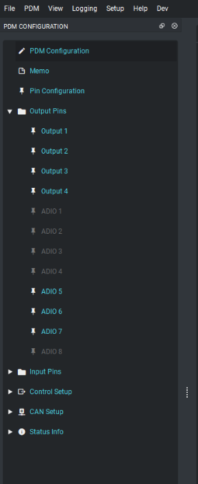
Selecting View>PDM Configuration will produce the configuration tree on the left-hand side of the page.
The Basic Configuration tab contains the following settings:
- PDM Name. If more than one PDM is being used this is where the user identifies them for later configuration.
- PDM Output Enable. This setting is a temporary override that disables all high and low power outputs, while still allowing them to be configured in software.
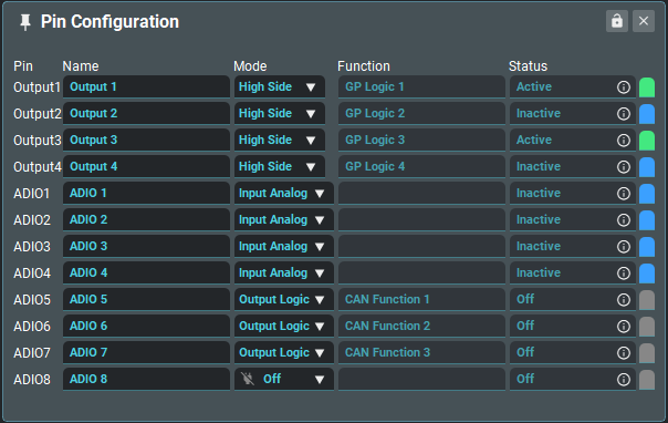
¶ Pin Configuration
This is where all pins can be viewed quickly and have their names and modes set.
Once the pin modes have been defined they will be available in the respective menus, Outputs Pins or Input Pins, for setup.
- Once configured, the function that controls the pin will become available in the Pin Configuration box under Function.
¶ High Power Output Pins

| Functions | Shows the list of connected function(s). Multiple functions controlling one pin is not normally recommended. |
| Mode |
Sets pin mode
|
| Status | Shows the current status of the pin, and may be used to control subsequent GP Logic, Math or GP Function blocks. |
| Test Mode |
Setting to a test mode (Active or PWM) will turn the output status to active and override any function using this pin.
|
Protection
| Mode |
Sets fuse mode
|
| Inrush Limit + Trip Time + Duration |
When the pin switches active, the 'Inrush Limit' will be used for the 'Duration' period. The output will go into a fault state if it exceeds the 'Inrush Limit' for longer than the 'Trip Time'. When configured as a half/full bridge, 'Duration' is disabled. The Inrush Limit will be continuously monitored. |
| Overcurrent Limit + Trip Time |
Normal fuse trip current in Amps. If a current value higher than 'Overcurrent Limit' is detected for longer than the 'Trip Time' period, the pin will enter a Fault state. If configured as a high/low side driver, the 'Overcurrent Limit' will only be used after the 'Inrush Duration' has finished. |
| Retry Count + Delay | Retry Counter. With 'Retry' Protection Mode enabled, and under fault conditions, the pin will attempt to switch Active, up to 'Retry Count' times. After 'Retry Count' attempts, the pin will remain Inactive until a setting is changed or the next power cycle. |
| Over-Temp Limit |
If the PDM reaches an internal temperature greater than the 'Over-Temp Limit', this pin will go into the Fault state. This feature is used to perform staged thermal shutdown on a pin-by-pin basis, typically activated only for low-priority output pins. |
| Safety |
Set whether or not this output can be turned off by the Safety Override.
|
¶ ADIO Pins
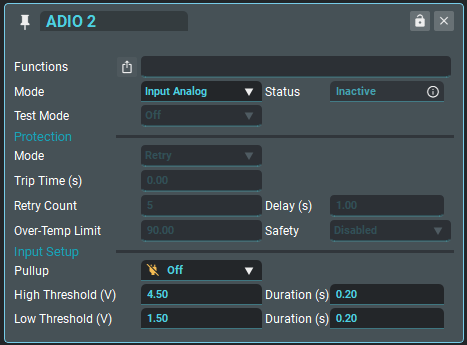
| Functions | Shows the list of connected function(s). Multiple functions controlling one pin is not normally recommended |
| Mode |
Sets pin mode
|
| Status | The status output shows the current status of the pin, and may be used to control subsequent GP Logic, Math or GP Function blocks. |
| Test Mode |
Setting to a test mode (Active or PWM) will turn the output status to active and override any function using this pin.
|
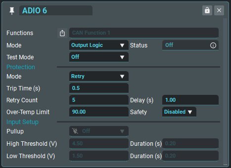
Protection - Active only in Output Mode
| Mode |
Sets fuse mode
|
| Trip Time |
Fuse trip timing in seconds. When the pin switches to active, if a current value higher than 8A is detected for longer than the 'Trip Time' period, the pin will enter a Fault state |
| Retry Count | Retry counter. With 'Retry' Fuse Mode enabled, and under fault conditions, the pin will attempt to switch Active, up to 'Retry Count' times. After 'Retry Count' attempts, the pin will remain Inactive until a setting is changed or the next power cycle |
| Delay | Retry delay. With 'Retry' Fuse Mode enabled, and under fault conditions, the pin will wait for 'Delay' seconds before trying to switch active again. |
| Over-Temp Limit |
If the PDM reaches an internal temperature greater than the 'Over-Temp Limit', this pin will go into the Inactive state. This feature is used to perform staged thermal shutdown on a pin-by-pin basis, typically activated only for low-priority output pins. |
| Safety |
Set whether or not this output can be turned off by the Safety Override.
|
Input Setup - Active only in Input Mode
| Pullup | Enables an internal 4.7k pullup resistor, to sensor 5V. |
| High Threshold + Duration |
When the pin voltage exceeds Threshold High (V) for at least Duration (s), the pin state is set to Active. ⭐When an ADIO is set as an output, the input voltage is fixed at 0V. |
| Low Threshold + Duration |
When the pin voltage is less than Threshold Low (V) for at least Duration (s), the pin state is set to Inactive. ⭐When an ADIO is set as an output, the input voltage is fixed at 0V. |
¶ Control Function Setup
This is where the configured pins are connected to each other.
This is where the pins can be turned on and off manually. You can use this to:
- Test outputs, and set pins to come on and stay on when the ignition is turned on.
Simply select output pin and state. Frequency and Duty Cycle can also be adjusted.
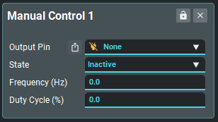
| Output Pin | Choose which pin to turn on. This will overwrite all settings made previously. |
| State | Set to active to turn on, Inactive to turn off. |
| Frequency | Set desired frequency |
| Duty Cycle | Set desired duty cycle |
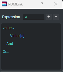
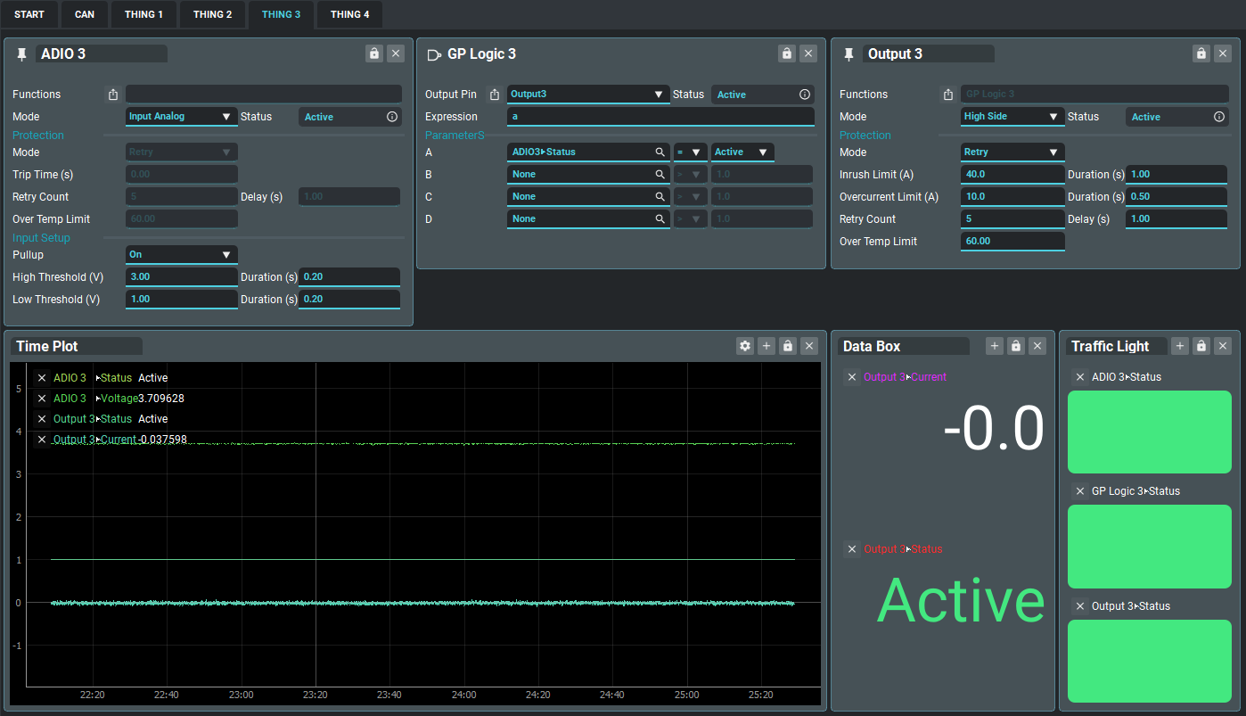
¶ GP Logic
GP Logic blocks allow a pin to be controlled directly by the combination of up to 4 input parameters, according to an Expression and the resulting Status value. The expression has a 40-character limit.
- If no pin is selected (Output Pin is set to None), then the Status of the GP Logic block may be used in other GP Logic, GP Function or Math Blocks to create more complex functions.
The standard "Math Block Expression Syntax" as found in the Link G4x, is used to connect the parameters. For example:
- a results in logic parameter A being returned in the Status output
- a&b results in the combination of logic parameters A AND B being returned in the Status output
- a|b results in the combination of logic parameters A OR B being returned in the Status output
- a&!b results in the combination of logic parameters A AND (NOT B) being returned in the Status output
- (a&b)|(c&d) results in the combination of logic parameters (A AND B) OR (C AND D) being returned in the Status output
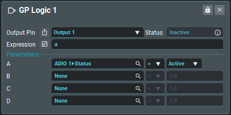
| Output Pin | Choose which pin to control. If not set, the GP Logic block may be used via its Status output. |
| Status | Shows the Status of the Expression |
| Expression | An Expression Math Block Expression Syntax. The value of parameters below may be referenced via the variables a, b, c and d |
| Parameter A | Evaluates the selected parameter, operator and value, resulting in a True/False value stored in variable a |
| Parameter B | Evaluates the selected parameter, operator and value, resulting in a True/False value stored in variable b |
| Parameter C | Evaluates the selected parameter, operator and value, resulting in a True/False value stored in variable c |
| Parameter D | Evaluates the selected parameter, operator and value, resulting in a True/False value stored in variable d |
¶ GP Logic Editor
Any GP Logic Expression can be edited directly using the expression box or by using this text-based editor.
The editor can be opened by clicking the button to the left of the Expression input listed above.
| Expression | A Logic Block Expression Syntax. The value of parameters below may be referenced via the variables a, b, c and d. Uses the same logical syntax as a Math Block. |
| + | Add a new operator after the selected location |
| - | Remove the selected operator from the expression |
¶ GP Functions
GP Function blocks allow a pin to be controlled directly by a GP Logic, CAN Stream, CAN Keypad, or Math block via its Condition Parameters.

| Output Pin | Choose which pin to control |
| Condition Parameters |
Select a status variable, an operator and a value. The resulting status controls the Output pin
|
| Holdoff | Sets a delay time. Waits this many seconds before changing the output State to Active. |
| Pulse | The condition must evaluate to False for at least the Pulse time before the Inactive state is set on the Output |
| Freq Param | When not None, sets the output PWM frequency cycle to the value set by the selected parameter. In this case, the Freq Value setting is not used. |
| Freq Value | When Freq Param is None, sets a fixed frequency PWM output. |
| Duty Param | When not None, sets the output PWM frequency cycle to the value set by the selected parameter. In this case, the Duty Value setting is not used. |
| Duty Value |
When Duty Param is None, sets a fixed Duty Cycle PWM output. Set to 100% to make the Output pin follow the Condition Status. |
¶ Timers
Timers are used to generate low-speed output pulses or generate timing count values which may be used by GP Logic, GP Function or Math blocks to perform complex timed functions.

| Output Pin | Choose which pin to control. If not set, the timer may be used via its Status output. |
| Status |
Timer status:
|
| Mode |
Sets the timer mode:
|
| Time | Time in seconds since trigger. Rolls over to 0 every Holdoff + Pulse timing period. |
| Trigger |
When the logical expression (Parameter, Operator, Value) results in an Active status result, the timer is triggered. ⭐Edge operators function upon a parameter change. |
| Holdoff | Time to wait before going to the Triggered/Active state. |
| Pulse | Time to wait before going to the Inactive state after a successful trigger. |
| Count | The count of pulses generated by the timer. |
| Counter Reset | Select a parameter, operator and value that, when evaluated as true, reset the Timer Count |
¶ Safety Override
The Safety Override function gives the user the ability to turn off output(s) when a parameter reaches a certain value, no matter what other function is assigned to the same pin.
⭐ Safety also needs to be enabled in the Output/ADIO settings menu for each output you wish to override.
⭐ The output Test Mode will override this function if both have been enabled/turned on.
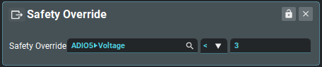
| Safety Override Expression | Select a parameter, operator and value that, when evaluated as true, turns all outputs with Safety enabled off. |
¶ Math Blocks
Math blocks are the most powerful Arbitrary Math and Logic Block available. The math block runs a language processor that can evaluate many C language operators and functions. The expression has a 40 character limit.
- Math AND Logic expressions may be combined.
- Many special functions are available. See the Math Block Expression Syntax guide below.
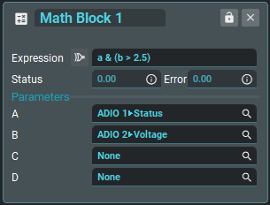
| Expression | A Math Block Expression Syntax. The value of parameters below may be referenced via the variables a, b, c and d |
| Status | Indicates the result of the Expression. For math expressions, the Status is a number. For logical expressions, the Status is reduced to the values 0, or 1. |
| Error | When the Error is not 0, the Expression has resulted in an error or cannot be computed. This happens most often when the expression is invalid. |
| Parameter A | the selected parameter value is stored in variable a |
| Parameter B | the selected parameter value is stored in variable b |
| Parameter C | the selected parameter value is stored in variable c |
| Parameter D | the selected parameter value is stored in variable d |
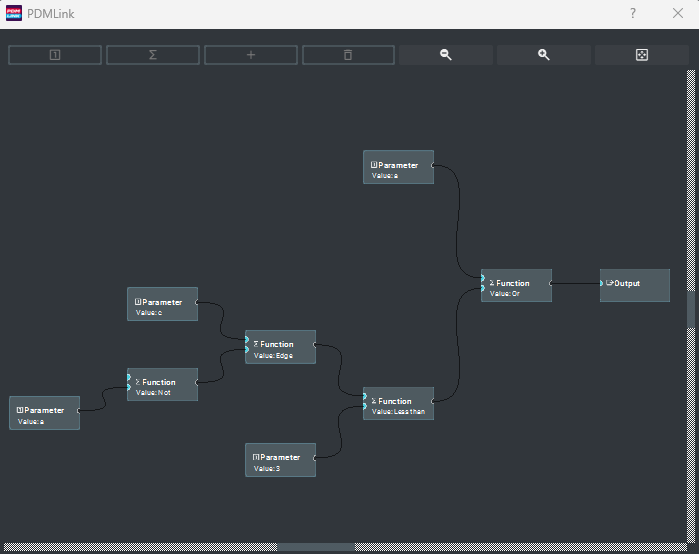
¶ Math Expression Viewer
Math and Logic Expressions can be viewed in a graphic form by clicking to the left of the expression input.
Each block represents a component of the expression and allows a visual overview of any expression
¶ Math Block Expression Syntax
All Math and Logic blocks support the following functions set.
- Parameters a, b, c and d reflect the current value of any ECU runtime value.
- The equation is calculated at a rate of 1kHz.
- The equation may contain any combination of math functions, up to 20 characters.
- Parameters are sampled at the time of calculation.
In the tables below:
- param/param1/param2 may be set to any of parameters a, b, c or d.
- param/param1/param2 may be set to any number value.
¶ Logic Operators
| Function | Syntax | Example | Description |
|---|---|---|---|
| ! (not) | !param |
!1 = 0 !100.1 = 0 !0 = 1 |
!a results in 0 if a is not zero, and 1 if a is zero. |
| & (and) | param1¶m2 |
5&9 = 1 5&0 = 0 |
a&b results in 0 if either a or b is zero, otherwise 1.
|
| | (or) | param1|param2 |
5|9 = 1 5|0 = 1 |
a|b results in 1 if either a or b is 1, otherwise 0. |
| ^ (xor) | param1^param2 |
5^9 = 0 5^0 = 1 0^1 = 1 0^0 = 0 |
a^b results in 1 if one of a or b is non zero, otherwise 0 if a and b are both 0 or both non zero. |
|
= (equal) == (equal) |
param1=param2 or param1==param2 |
a=b results in 1 if a and b are equal a==b is equivalent to a=b |
|
| != (not equal) | param1!=param2 | a!=b results in 1 if a and b are NOT equal | |
| > (greater than) | param1>param2 |
5>9 = 0 5>0 = 1 |
a>b results in 1 if a is greater than b, otherwise 0.
|
| < (less than) | param1<param2 |
5<9 = 1 5<0 = 0 |
a<b results in 1 if a is less than b, otherwise 0. |
| >= (greater than or equal) | param1>=param1 |
5>=5 = 1 5>=0 = 1 5>=6 = 0 |
a>=b results in 1 if a is greater than or equal b, otherwise 0.
|
| <= (less than or equal) | param1<=param2 |
5<=5 = 1 5<=0 = 0 5<=6 = 1 |
a<=b results in 1 if a is less than or equal to b, otherwise 0. |
¶ Math Operators
| Function | Syntax | Example | Description |
| * (multiply) | param1*param2 | 5*9 = 45 | a*b results in the multiplication of parameters a and b. |
| / (divide) | param1/param2 | 5/9 = 0.556 |
a/b results in parameter a divided by parameter b.
|
| % (modulus) | param1%param2 |
4%5 = 4 5%5 = 0 6%5 = 1 |
a%b results in the modulus of parameters a and b. Modulus computes the remainder of a divided by b.
if parameter a is counting up continuously, 0,1,2,3,4,5,6,7,8,9 ... then a%4 results in 0,1,2,3,0,1,2,3,0,1,2,3 ... the example (int(t)%4)+1 results in 1,2,3,4,1,2,3,4,1,2,3,4... on a count of 1 per second
|
| + (add) | param1+param2 | 5+9 = 14 | a+b results in the addition of parameters a and b. |
| - (subtract) | param1-param2 | 5-9 = -4 | a-b results in the subtraction of parameters a and b. |
| () (braces) | param1*(param2+param3) |
10*(287+1000) = 12870 10*287+1000 = 3870 |
Controls the order of precedence in calculations. |
¶ Special Functions
| Function | Syntax | Example | Description |
| if | if(param, then, else) |
if(a>4, b, b*5) = b if a>4 =b*5 otherwise |
returns the "then" value if the "param" value is true, otherwise results in the "else" value. Any number of if() statements can be added to an expression. |
| peak | pk(param, timeout) | pk(a, 1.0) |
Holds the peak value of parameter a. if the value of parameter a. does not change within the timeout (in seconds) the peak is set to the current value of a. If the timeout is 0, the peak is held indefinitely.
|
| delta | dt(param, time) | dt(a, 1.0) |
Holds the delta value of parameter a, taken over the time specified (in seconds).
|
| average | av(param, time) | av(a, 1.0) |
Holds the average value of parameter a, taken for 20 evenly spaced samples over the time specified (in seconds).
|
| time | t | Holds the value of time in seconds since PDM startup. | |
| Counter | cnt(param) | cnt(a) |
Tree running time counter. Starts counting up, once per 10 milliseconds, as long as parameter a is not 0. When parameter a is 0, the counter is reset to 0.
|
| edge | ed(param1, param2) | ed(a, b) |
Edge counter. Counts rising edges on parameter a, as it passes from less than 1 to greater than or equal to 1. When parameter b is 0, the counter is reset to 0.
|
¶ Numeric Functions
| Function | Syntax | Example | Description |
| integer | int(param) |
int(1.1) = 1 int(t) = time in seconds (without decimal) |
removes the decimal places from parameter, resulting in an integer. |
| bool | bool(param) |
bool(2.5) = 1 bool(0) = 0 |
Forces any number or result value that is not 0, to 1. otherwise returns 0. |
| min | min(param1, param2) | min(a, b) | results in the value of a or b, whichever is smallest. |
| max | max(param1, param2) | max(a, b) | results in the value of a or b, whichever is largest. |
| compare | cmp(param1, param2) | cmp(a, b) | results in: -1 if a < b, 1 if a > b, 0 if a = b |
| round | round(param, decimals) | round(1.01258, 2) = 1.01 | results in the value of the parameter, rounded to the number of decimals specified. |
| Absolute value | abs(param) |
abs(-25.6) = 25.6 abs(25.6) = 25.6 |
abs(a) results in a positive number no matter if a is positive or negative. |
| ceiling | ceil(param) |
ceil(-25.6) = -25 ceil(25.6) = 26 |
ceil(a) results in the smallest integer that is greater than or equal to a (i.e : rounds up to the nearest integer). |
| floor | floor(param) |
floor(-25.6) = -26 floor(25.6) = 25 |
floor(a) results in the smallest integer that is smaller than or equal to a (i.e : rounds down to the nearest integer). |
| exponential | exp(param) | exp(6) = 403.428 | exp(a) results in the value of e (Euler's number), to the power of a. |
| logarithm, natural | ln(param) | ln(2) = 0.693 | ln(a) results in the natural log of a. |
| logarithm, base 10 | log(param) | log(2) = 0.301 | log(a) results in the log base 10 of a. |
| power | pow(param1, param2) | pow(6, 2) = 36 | pow(a, 2) results in a to the power of 2. |
| square root | sqrt(param) | sqrt(25) = 5 | sqrt(a) results in the square root of a. |
| cosine | cos(param) | cos(pi) = -1 | cos(a) results in the trigonometric cosine of a. |
| sine | sin(param) | sin(pi) = 0 | sin(a) results in the trigonometric sine of a. |
| tangent | tan(param) | tan(pi) = 0 | tan(a) results in the trigonometric tangent of a. |
| power | pow(a, b) | pow(a, 2) | pow(a, 2) results in the value of parameter a being raised to the power of 2. If a=4, the result would be 16. |
| constant, e | e | e = 2.71828 | Euler's number, a special constant |
| constant, pi | pi | pi = 3.14159 | Pi, a special constant. |
¶ PID Controllers
PID Controllers provide powerful position and rate control over DC motors, Linear motors, and Solenoids - applications may include Throttle body and e-Wastegate controllers.
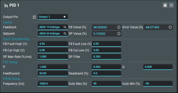
The output pin setting selects the output pin that is to be used.
¶ Inputs
| Feedback | PID Feedback input signal. Connect to an input pin, for example, ADIO1 State > Voltage, or a control parameter such as Math Block 1 > Result. Any PDM control parameter may be used. |
| FB Value | Monitor the feedback signal value - normalized from 0-100% |
| Error Value | Monitors PID target error value - from 0-100% |
| Setpoint | PID Setpoint input signal. Connect to an input pin, for example, ADIO1 State > Voltage, or a control parameter such as Math Block 1 > Result. Any PDM control parameter may be used. |
| SP Value | Monitors Setpoint signal error value- normalized from 0-100% |
¶ Input Conditioning
| FB Fault High | Signals a fault if the feedback input value exceeds 'FB Fault High' |
| FB Fault Low | Signals a fault if the feedback input value exceeds 'FB Fault Low' |
| FB Cal High | PID feedback (0-100%) is the ratio of 'FB value' as it falls between 'FP Cal High' (100%) and 'FP Cal Low' (0%) |
| FB Cal Low | PID feedback (0-100%) is the ratio of 'FB value' as it falls between 'FP Cal High' (100%) and 'FP Cal Low' (0%) |
| SP Max Rate | Maximal rate of change allowed on the setpoint input. If the setpoint input rises or falls at a greater rate than specified, then the rate of change is limited by the PID controller. This translates to the level of smoothing noted on the output PWM signal. |
| SP Filter | The degree of filtering applied on the setpoint input. |
¶ PID Setup
| P, I, D | Proportional, Derivative and Integral gain coefficients. |
| Feedforward | Feed-forward gain value |
| Deadband | Setpoint deadband. No PID response will be actioned while the change in setpoint is inside the deadband. |
¶ PWM Setup
| Frequency | Frequency of PID PWM output signal (Fixed) |
| Duty Max | The maximum duty cycle of PID PWM output signal from 0-100% |
| Duty Min | The minimum duty cycle of PID PWM output signal from 0-100% |
¶ CAN Setup
¶ ECU Setup
When connecting to a Link ECU, set up the ECU CAN as per the PCLink helpfile. G4X ECU Tuning Functions > CAN > Link Razor PDM
Ensure the latest version of PCLink is being used (V6.23 or later) and ensure the latest firmware has been installed.
- Select User Defined and in one of the channels select Link Razor PDM.
- Choose an ID that is not being used and a transmit rate.
- CAN Bus ID is in Decimal format.
There will be 5 IDs used. The one chosen and the four consecutive numbers following that ID.
ID = ECU transmit, ID + 1 = PDM1 IO Status, ID + 2 = PDM1 Keypad Counts, ID + 3 = PDM2 IO Status, ID + 4 = PDM2 Keypad Counts. This allows for up to 2 PDMs connected to the same Link ECU.
12 new runtimes (6 per PDM) have been added for currents, fault flags and status flags received by the ECU from the PDM.
CAN Aux 1 -16 are used to control the outputs on the PDM.
To setup a Link ECU to transmit the CAN Aux runtimes and receive basic PDM data:
- Open the CAN Setup window (PCLink > ECU Controls > CAN Setup).
- Select the CAN module to be used
- Set the Mode to 'User Defined'.
- Configure the Bit Rate to the same Bit Rate as the PDM (Often 1 Mbit/s).
- Select a spare CAN channel
- Select 'Link Razor PDM' from the Mode drop-down menu.
- Set the CAN ID to an appropriate spare Id, the selected ID doesn't matter as long as the PDM is set to match and the next 4 CAN Ids are free (e.g. if Id 500 is used 501 to 504 must also be free and unused).
- Set the Transmit Rate to 20Hz, this controls the rate at which the CAN Aux information is transmitted by the ECU, faster or slower rates can be used if desired.
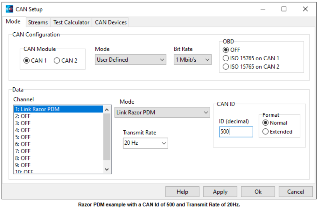
- Click Apply and then OK.
- Make sure a Store (F4) is performed.
To setup a Link ECU to use one or more of the Razor PDM's ADIO channels or Keypad Functions as an ECU CAN input:
- In PCLink connect to the ECU and open CAN -> PDM 1 in the ECU settings menu (or PDM 2, PDM 3 or PDM 4 depending on which PDM the input is coming from).
- Select the appropriate ADIO or Keypad Function's setting and set it to an unused CAN Freq, CAN An or CAN DI input.
- If all of the above CAN setups have been done correctly the selected CAN input should now show the status or value of the ADIO or Keypad function.
Note: Only ADIO 5-8 can be used as Frequency inputs.
Note: For CAN Keypad Functions a value of 1 or more is considered active when a CAN DI is selected.
¶ PDM Setup
¶ Basic CAN Configuration
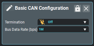
| Termination | Turns the PDM's terminating resistor On/Off. |
| Bus Data Rate | Sets the data rate of the PDM CAN bus. The data rate needs to be the same on all devices connected to the same bus. |
¶ CAN Channel Setup
This is the starting point when setting up CAN on the Razor PDM. Currently, these channels can be used to receive or transmit, depending on the Mode, CAN streams that are detailed below.
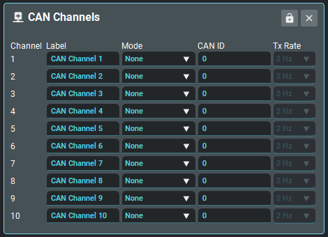
| Label | Whatever you wish to call each CAN Channel. By default they are set as CAN Channel 1 - 10. |
| Mode |
Sets the CAN Channel Mode:
|
| CAN ID | The CAN ID the channel will send every message on |
| Transmit Rate | How often the PDM will transmit the chosen message(s). Note: this is different to the Bus Data Rate. |
¶ CAN Function Setup
Setting a channel to the CAN Function mode allows the PDM to receive Status, Frequency and Duty cycle settings for an Output. The structure of the CAN stream is detailed below.
To use all of the CAN Functions, just set one CAN Channel to the CAN Function Mode. Any Output can be used with any CAN Function.
The easiest way to use CAN Functions is with a Link ECU but any device capable of transmitting over CAN can be used
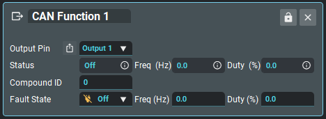
| Output Pin | The Output pin directly controlled by this CAN Function. If an Output is selected in this list, its Status, Frequency and Duty Cycle will change according to the received values. Alternatively, you can feed the received CAN values (Status, Freq, Duty) into other functions such as Math Blocks or PID control. |
| Status | Status value received from the incoming CAN message. Inactive=0, Active=1, Off=2, Fault=3 |
| Frequency | Frequency value received from the incoming CAN message. |
| Duty Cycle | Duty Cycle value received from the incoming CAN message. |
| Compound ID | The Compound ID in the first byte, used to choose which frame in the CAN stream to use. For example, the Link ECU PDM CAN stream will send CAN Aux 1 information with a compound ID of 0. |
| Fault State | State the CAN Function will change to if a CAN message has not been received for 2 seconds (and at least one has been received since power up). |
| Fault Frequency | Frequency the CAN Function will change to if a CAN message has not been received for 2 seconds (and at least one has been received since power up). |
| Fault Duty Cycle | Duty Cycle the CAN Function will go to if a CAN message has not been received for 2 seconds (and at least one has been received since power up). |
To setup the Link Razor PDM to receive the CAN Aux information:
- Open PDMLink and connect to the PDM (F3 or PDM dropdown menu -> Connect).
- Open CAN Setup -> Basic CAN Configuration
- Configure the Bit Rate to match the ECU (Often 1 Mbit/s).
- Open CAN Setup -> CAN Channels.
- Select a spare CAN channel.
- Select 'CAN Function' from the Mode drop-down menu.
- Set the CAN ID to match the 'Link Razor PDM' Id in the ECU CAN Setup.
- Set the Transmit Rate to None, this Mode only receive's data from the ECU and doesn't transmit any data.
- Make sure a Store (F4) is performed.
- Further setup is required in PDMLink to assign CAN Aux's from the ECU to CAN Function's in the Razor PDM before they can be used to control outputs. See GP Functions.
To setup the Link Razor PDM to transmit Pin Status and Current flow information to a Link ECU:
- Open PDMLink and connect to the PDM (F3 or PDM dropdown menu -> Connect).
- Open CAN Setup -> Basic CAN Configuration
- Configure the Bit Rate to match the ECU (Often 1 Mbit/s).
- Open CAN Setup -> CAN Channels.
- Select a spare CAN channel.
- Select 'IO Status Stream' from the Mode drop-down menu.
- Set the CAN ID the ECU's 'Link Razor PDM' Id +1 if this PDM 1 in the ECU, +3 if this is PDM 2 in the ECU, +5 if this is PDM 3 in the ECU or +7 if this is PDM 4 in the ECU (e.g. if the ECU's 'Generic PDM' Id is 500 use Id 501 for PDM 1, Id 503 for PDM 2, Id 505 for PDM 3 or Id 507 for PDM 4).
- Set the Transmit Rate to 20Hz, faster or slower rates can be used if desired.
- Make sure a Store (F4) is performed.
- Current and pin status information should now show up in the ECU, these runtime values and statuses are explained more in the ECU Helpfile.
To setup the Link Razor PDM to transmit CAN Keypad states and values to a Link ECU:
- Open PDMLink and connect to the PDM (F3 or PDM dropdown menu -> Connect).
- Open CAN Setup -> Basic CAN Configuration
- Configure the Bit Rate to match the ECU (Often 1 Mbit/s).
- Open CAN Setup -> CAN Channels.
- Select a spare CAN channel.
- Select 'Keypad Counts' from the Mode drop-down menu.
- Set the CAN ID the ECU's 'Link Razor PDM' Id +2 if this PDM 1 in the ECU, +4 if this is PDM 2 in the ECU, +6 if this is PDM 3 in the ECU or +8 if this is PDM 4 in the ECU (e.g. if the ECU's 'Generic PDM' Id is 500 use Id 502 for PDM 1, Id 504 for PDM 2, Id 506 for PDM 3 or Id 508 for PDM 4).
- Set the Transmit Rate to 20Hz, faster or slower rates can be used if desired.
- Make sure a Store (F4) is performed.
- The PDM's keypad data can now be used via CAN DIs or CAN Analog inputs as selected in the PDM's Keypad function settings.
¶ Keypad Setup
¶ Keypad Settings
Up to two CAN Keypads can be used on a Razor PDM. The list of supported models are detailed below.
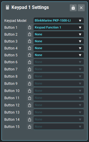
| Keypad Model | The model of the CAN Keypad. Changing the model will allow different numbers of buttons to be used e.g. a 5 button keypad will let you choose the function on buttons 1 - 5 |
| Button | Choose which Keypad Function is used to control each button on the keypad. |
¶ Keypad Function
A Keypad Function determines how a button on the CAN keypad behaves.
There are 15 functions in total which can be used entirely on one keypad, or shared across two. Each function can have its label changed to describe its use.
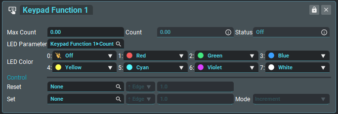
| Max Count |
This button counts up once per press and rolls over to 0 at Max Count.
|
| LED Parameter | Parameter that determines which LED state to use for visual feedback. |
| LED Colour | Sets the button colour/state that is shown when the LED Parameter is equal to a number from 0 to 7. |
| Count | Count holds the number of presses |
| Status | Status is Active only when the button is pressed. |
| Reset Expression | Select a parameter, operator and value that, when evaluated as true, reset the Keypad Function Count |
| Set Expression | Select a parameter, operator and value that, when evaluated as true, increment or decrement the Keypad Function Count. Allows two buttons to increment/decrement a single count. |
| Set Mode | Determines whether the Set Expression increments or decrements. |
¶ CAN Stream Structure
The tables below describe how the data in CAN streams on the PDM are transmitted and received on the Link Razor PDM. This information is useful when interacting with a device that does not have built in Link Razor PDM functionality.
The structure used is based on the CAN Channel Mode. All data is sent/received with the most significant byte first.
¶ CAN Function
| Byte 0 (Unsigned) | Byte 1 (Unsigned) | Byte 2 & 3 (Unsigned) | Byte 4 & 5 (Unsigned x100) | Byte 6 & 7 |
|---|---|---|---|---|
| Compound ID | Status | Frequency (Hz) | Duty Cycle (%) | Unused |
¶ IO Status
| Frame Number | Byte 0 (Unsigned) | Byte 1 (Unsigned) | Byte 2 (Unsigned) | Byte 3 (Unsigned) | Byte 4 & 5 (x100) | Byte 6 & 7 (Signed x100) |
|---|---|---|---|---|---|---|
| Frame 1 | 0 | HP Output 1 Status | HP Output 1 Frequency (Hz) | HP Output 1 Duty Cycle (%) (Signed) | HP Output 1 Current (A) | |
| Frame 2 | 1 | HP Output 2 Status | HP Output 2 Frequency (Hz) | HP Output 2 Duty Cycle (%) (Signed) | HP Output 2 Current (A) | |
| Frame 3 | 2 | HP Output 3 Status | HP Output 3 Frequency (Hz) | HP Output 3 Duty Cycle (%) (Signed) | HP Output 3 Current (A) | |
| Frame 4 | 3 | HP Output 4 Status | HP Output 4 Frequency (Hz) | HP Output 4 Duty Cycle (%) (Signed) | HP Output 4 Current (A) | |
| Frame 5 | 4 | ADIO 1 Status | ADIO 1 Frequency (Hz) | ADIO 1 Duty Cycle (%) (Unsigned) | ADIO 1 Voltage (V) | |
| Frame 6 | 5 | ADIO 2 Status | ADIO 2 Frequency (Hz) | ADIO 2 Duty Cycle (%) (Unsigned) | ADIO 2 Voltage (V) | |
| Frame 7 | 6 | ADIO 3 Status | ADIO 3 Frequency (Hz) | ADIO 3 Duty Cycle (%) (Unsigned) | ADIO 3 Voltage (V) | |
| Frame 8 | 7 | ADIO 4 Status | ADIO 4 Frequency (Hz) | ADIO 4 Duty Cycle (%) (Unsigned) | ADIO 4 Voltage (V) | |
| Frame 9 | 8 | ADIO 5 Status | ADIO 5 Frequency (Hz) | ADIO 5 Duty Cycle (%) (Unsigned) | ADIO 5 Voltage (V) | |
| Frame 10 | 9 | ADIO 6 Status | ADIO 6 Frequency (Hz) | ADIO 6 Duty Cycle (%) (Unsigned) | ADIO 6 Voltage (V) | |
| Frame 11 | 10 | ADIO 7 Status | ADIO 7 Frequency (Hz) | ADIO 7 Duty Cycle (%) (Unsigned) | ADIO 7 Voltage (V) | |
| Frame 12 | 11 | ADIO 8 Status | ADIO 8 Frequency (Hz) | ADIO 8 Duty Cycle (%) (Unsigned) | ADIO 8 Voltage (V) | |
| Frame 13 | 50 | PDM Temperature (+50) | PDM Voltage (x10) | Unused | Unused | Unused |
¶ Keypad Counts
| Frame Number | Byte 0 (Unsigned) | Byte 1 (Unsigned) | Byte 2 (Unsigned) | Byte 3 (Unsigned) | Byte 4 (Unsigned) | Byte 5 (Unsigned) | Byte 6 & 7 |
|---|---|---|---|---|---|---|---|
| Frame 1 | 0 | Keypad Function 1 Count | Keypad Function 2 Count | Keypad Function 3 Count | Keypad Function 4 Count | Keypad Function 5 Count | Unused |
| Frame 2 | 1 | Keypad Function 6 Count | Keypad Function 7 Count | Keypad Function 8 Count | Keypad Function 9 Count | Keypad Function 10 Count | Unused |
| Frame 3 | 2 | Keypad Function 11 Count | Keypad Function 12 Count | Keypad Function 13 Count | Keypad Function 14 Count | Keypad Function 15 Count | Unused |
¶ Visualizations
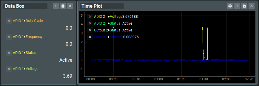
¶ Data Monitors
Data monitoring visualizations can be found live, by either right-clicking or double clicking the background.
Stretch Lists Traffic Light indicators Bar Gauges

Vertical Lists Time Plots
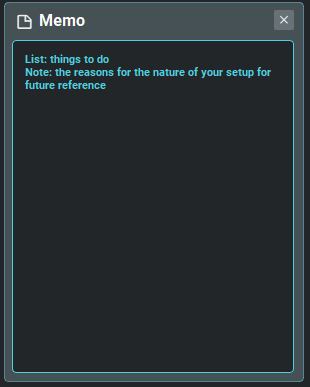
¶ Text Memos
Memos can be added to any to any tab - as many as you want. Right-click, or Double click the background, to add a new memo box.
- Memos are stored in either/both exported layout files (.pdml), and saved in PDM configuration files (.pdmc)
¶ Logging
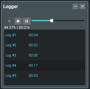
PDMLink can be used to log and playback data. Use Menu>Logging>Tools to open the logger toolbox.
A new Log record is made every time you click the record button. Records are kept in a numbered sequence and can be saved to disk as a single file (.pdmlog) for future reference.
- logs can be opened and played back in real-time.
- Any useful visualizations can be opened live, as the log playback system mimics a live connected PDM.
¶ UI and General Tips
¶ Settings and Configuration
All PDM settings may be accessed through the configuration tree. See Menu>PDM>Configuration OR Right click OR double click the background to open the tree.
- Grayed-out items are shown as such according to their configuration.
- Many Items may be renamed - double click an item in the setting tree to rename it (requires Enter Key to save name)
¶ Settings Boxes and Visualizations
Most items - Functions, Pins, and Visualizations, can be renamed to make your configuration/purposes clear. Remember that these require the Enter Key to save your changes.

¶ Layouts
PDMLink is a graphically oriented system. It is encouraged that users take a small amount of time to create useful layouts that make the configuration flow easier each time.
- Layouts are saved along with the PDM configuration inside the .pdmc (PDM configuration) file.
- Layouts may also be exported for sharing independent of the configuration via the Menu>View>Layout>Export option.
- Use Tabs to simplify workflows - less on a page is better
- Multiple Layouts can be saved directly within the software use Menu>View>Layout>New to create new layouts. Use Menu>View>Layout>Switch to flip between them.
¶ Cut Copy Paste
Settings Boxes and Visualizations support some features to help make layout building easier.
- CTRL+c, CTRL+x CTRL+v are supported on all settings visualization views
- Multi-select (CTRL+Click) is supported for drag and cut/copy/paste
- Cut/Copy Paste operations are supported between tabs, layouts and instances of the application
¶ Themes
User configurable colour/font themes are coming soon.
¶ User Preferences
Use Menu>Setup>Preferences to access Application settings.
| Colour Theme | Sets the colour scheme for the application |
| Snap Grid | A value in pixels, to which user settings boxes and visualizations will snap |
| Snap Gap | A value in pixels, adds a gap between user settings boxes and visualizations |
| Plot Length | The time to show data for in plots, in seconds. Very long times may result in performance issues. |
| Display Update Rate |
The number of seconds between display updates. Very short times may result in performance issues. ⭐Does not affect logging rates. |
| Popup Fade Timer | Time before non-critical message boxes disappear. |
| Opacity | Sets the opacity of settings boxes and visualizations (10-100%) |
| Show Units | Show or hide units in all areas of the UI |
| Open Sidebar on Connect | Opens the PDM Configuration menu on connect. |
| Allow Duplicates | Allows duplicate settings boxes (duplicated across tabs), or if disabled, snaps to the open settings box no matter which tab it is on. |
| Connect on Start | Connect to a PDM when the application opens. |
| Auto Connect | Automatically connect to a PDM, if one is plugged in. |
| Language | TBD |
¶ Support and Troubleshooting
¶ In-Application Help
PDMLink has links to the online help (This website) in the Menu>Help Menu as well as a PDF copy of this help.
¶ Technical Support
You can contact your nearest Link dealer for help, the Link dealer list can be found at linkecu.com/dealers/dealer-network/
Link Technical Support may be reached through the contacts on the Link website linkecu.com/software-support/
¶ Lifetime Warranty
LINK ENGINE MANAGEMENT LTD – LIMITED LIFETIME WARRANTY
All Engine Control Units (ECUs) manufactured or distributed by Link Engine Management Ltd are subject to the following LIMITED LIFETIME WARRANTIES, and no others.
Link Engine Management Ltd warrants only to the original purchaser of the ECU, for the lifetime of the ECU, (subject to the limitations set out below), that the ECU shall be free from defects of
materials and workmanship in the manufacturing process. This warranty ceases to apply and does not apply to ECUs that have not been manufactured or distributed by Link Engine Management Ltd for a period of greater than one year.
An ECU claimed to be defective must be returned to the place of purchase. Link Engine Management Ltd, at its sole option, may replace the defective ECU with a comparable new ECU or repair the defective ECU.
This limited lifetime warranty is not transferable and does not apply to any ECU not properly installed or properly used by the purchaser or end user, or to any ECU damaged or impaired by external forces. The above warranties are the full extent of the warranties available on the ECU. Link Engine Management Ltd has no liability to the original purchaser or any other person for any loss, injury or damage to persons or property resulting from the use of the ECU or any failure of or defect in the ECU whether by general, special, direct, indirect, incidental, consequential, exemplary, punitive, or any other damages of any kind or nature whatsoever. Link Engine Management Ltd specifically disclaims and disavows all other warranties, express or implied, including, without limitation, all warranties of fitness for a particular purpose, warranties of description, warranties of merchantability, trade usage or warranties of trade usage.
For off-road use only, not intended for highway vehicles. This ECU contains a user-configurable software programme, which is updated by Link Engine Management Ltd from time to time. The user must ensure the current correct version of this programme is downloaded from the website of Link Engine Management Ltd and installed in the ECU prior to use. This limited lifetime warranty does not apply where the ECU has been installed with the incorrect version of the software programme. The user is solely responsible for the setup and testing of all user-configurable features.
Link Engine Management Ltd License Agreement
The software programme in this ECU is licensed not sold. Link Engine Management Ltd grants the user a license for the programme only in the country where the programme was acquired. No other rights are granted under this license and the programme may only be used on one machine at a time. If the programme is transferred a copy of this license and all other documentation must be transferred at the same time. The license may be terminated by the user at any time. Link Engine Management Ltd may terminate the licence if the user fails to comply with the terms and conditions of this license. In either event, the copy of the programme must be destroyed.